
I think the main focus for this post will be about the controls for the Arcade. There was a lot of effort put into getting them working, wired and laid out usefully. For starters I actually purchased the joysticks and buttons a year before starting this project. I got the whole set with controller board from X-Arcade They sell full button kits or you can get a piece at a time. I like the quality of their parts and don't have any complaints other than cable length which I will get into.
Pre-Layouts & Testing:
Once I decided on starting this project and decided on the Raspberry Pi as the PC I wanted to test out the buttons as I had never worked with them before and also make sure I could get them to work with the Pi. The one simple thing x-arcade did was the board treats the buttons and joysticks as a keyboard so pressing any of them is equal to pressing say W on a keyboard to go forward in a game.


So to test them I actually built them into an empty shipping box because it was stiff enough to not flex but light and thin enough to cut and move around. This method actually worked pretty well. I actually tried to test them just laid out on the table and that turned into a nightmare. Wires and buttons ever where.


Pre-Layouts & Testing:
Once I decided on starting this project and decided on the Raspberry Pi as the PC I wanted to test out the buttons as I had never worked with them before and also make sure I could get them to work with the Pi. The one simple thing x-arcade did was the board treats the buttons and joysticks as a keyboard so pressing any of them is equal to pressing say W on a keyboard to go forward in a game.
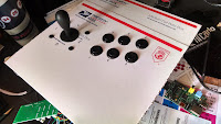
Here are a couple of pics of the buttons and joysticks


So to test them I actually built them into an empty shipping box because it was stiff enough to not flex but light and thin enough to cut and move around. This method actually worked pretty well. I actually tried to test them just laid out on the table and that turned into a nightmare. Wires and buttons ever where.
Couple of pics of the cardboard testing board


Once I had the buttons working with RetroPie I wanted to do a mock up using the MDF wood I decided to use. Again my reasoning behind this was it would give me an opportunity to work with the wood and discover anything to look for when doing the final build as I had not worked with MDF wood before. One of the main things I did discover when working with MDF wood is that when you drill your holes you need to have the board pressed against something (piece of scrap works) because if you just drill straight through MDF it likes to blow out on the backside which can cause some fitting issues. So I came up with the following which taught me a couple of lessons and let me see how well the buttons and everything fit in the MDF.


Once I was satisfied with out everything was working I started on the final build. Obviously you can skip the test wood build as its not 100% necessary. The next step was to decide on a final layout. I started looking for arcade button layouts on the internet. You could just square them up but I find that layout unnatural and hard on the fingers when playing. Luckily I was able to find a website (Slagcoin) that has a lot of different "typical" arcade layouts. I settled on the following as I felt it was kind of a natural hand fit. So I took the layout and enlarged it until it fit the size scale of the buttons I was using. This gave me a template I could then put on the wood and start drilling from.

Once I had my layout decided on and the MDF wood ready I set out to drill all the holes and attach/wire all the buttons. While trying to wire the buttons I learned that the wires they provided with the kit were just not long enough to allow a fit in the proper layout. (the issue I mentioned at the start) So I had to solder in wire extensions in to allow comfortable fit for everything. As the joystick needs to move you can't have the wires wrapped tight around the base. Also everything needs to reach the controller board which ends up being in-between the 2 sets of controls.


It was while building the button layout I finally decided on what to do for the "Coin Slot". I knew trying to fit a traditional coin slot mechanism would be difficult and probably have to go on the side of the box which I did not like or want to do. While surfing for ideas I came across a button set that looks like a coin return button that lights up. I found them at Groovy Game Gear site. They actually have a couple of options for the face of the buttons. I decided that these buttons would go on the front below the arcade controls which is traditional of most arcade machines. Wiring the button presses in was nothing special but I decided to wire the lights together and then right to the Raspberry Pi GPIO (Pins 2"5V" & 6"GND"). That way when the pi was off the lights would turn off.


In the next post I will be showing the actual build of the rest of the cabinet frame.
No comments:
Post a Comment